A Wastewater Treatment Plant (WWTP) is not a collection of isolated unit operations—it is a hydraulically, biologically, and mass-balance–constrained system. Every unit process influences downstream performance, and improper loading at any stage can destabilize the entire plant.
This article presents a complete end-to-end WWTP process walkthrough, focusing on engineering intent, governing equations, and design constraints.
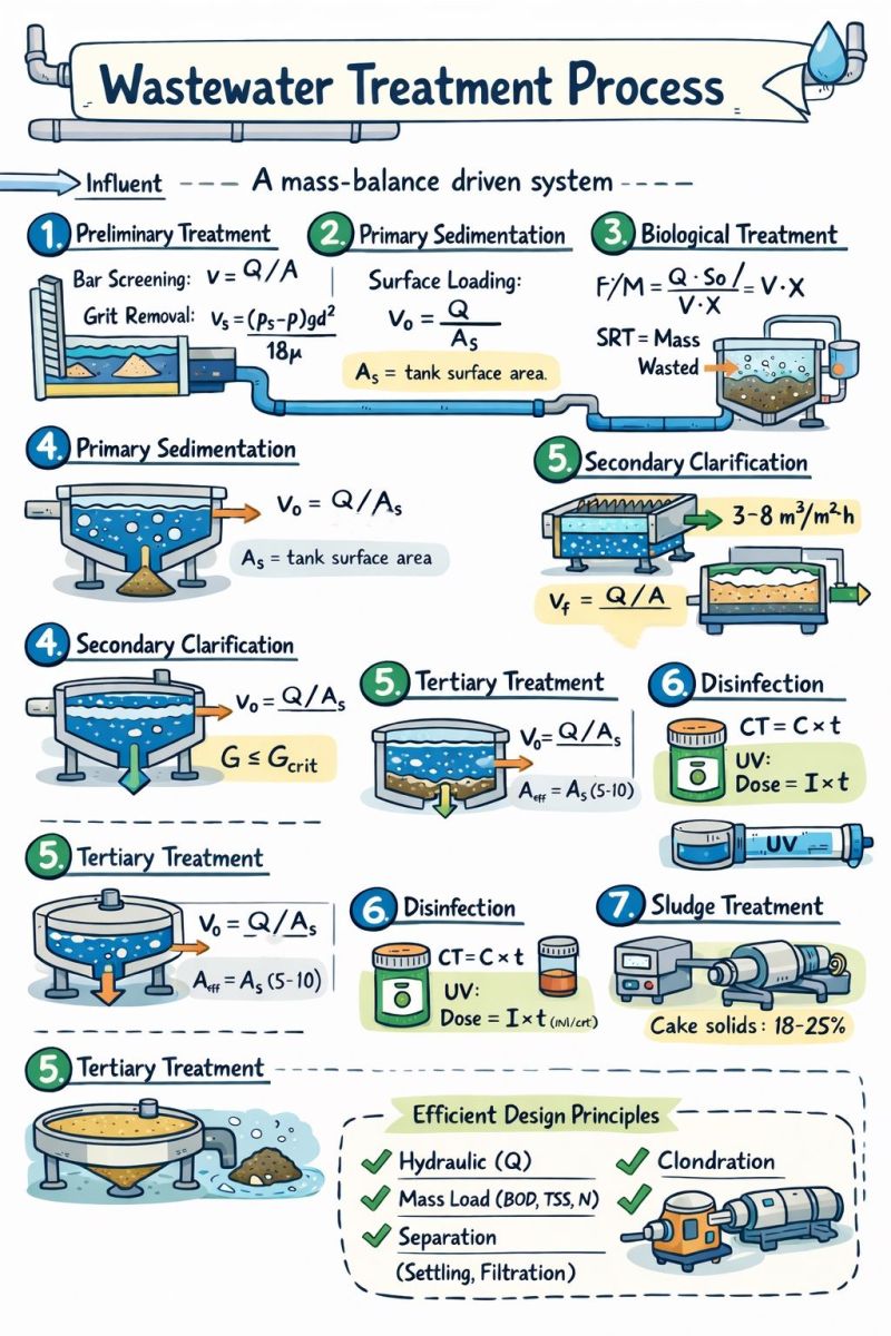
1️⃣ Influent & Preliminary Treatment
Purpose: Protect downstream equipment and stabilize hydraulic conditions.
Bar Screening
Screens remove large debris to prevent clogging and mechanical damage.
-
Velocity equation:
v = Q / A -
Design velocity: 0.6–1.0 m/s
-
Typical bar spacing: 6–40 mm
Maintaining adequate velocity avoids sediment deposition while preventing excessive headloss.
Grit Removal
Grit chambers remove dense inorganic particles (sand, gravel).
-
Settling velocity (Stokes’ Law):
vₛ = ((ρₛ − ρ) g d²) / (18 μ) -
Target particle size: ≥ 0.15–0.20 mm
Effective grit removal minimizes abrasion and volume loss in tanks.
2️⃣ Primary Sedimentation
Purpose: Remove settleable solids and reduce organic loading on biological units.
Hydraulic Design
-
Surface loading rate:
v₀ = Q / A = 0.8–1.2 m³/m²·h
Typical Performance
-
TSS removal: 50–70%
-
BOD₅ removal: 25–40%
Mass Balance
-
BOD_removed = Q × (C_in − C_out)
Primary clarifiers reduce oxygen demand and sludge production downstream.
3️⃣ Biological Treatment (Activated Sludge Process)
Purpose: Biodegradation of dissolved and colloidal organics.
Food-to-Microorganism Ratio (F/M)
-
F/M = (Q × S₀) / (V × X)
-
Typical range: 0.2–0.5 kg BOD/kg MLSS·d
Sludge Retention Time (SRT)
-
SRT = (Mass of solids in system) / (Daily solids wasted)
-
Carbon removal: 3–8 days
-
Nitrification: 8–20 days
Oxygen Requirement
-
O₂ demand ≈ 1.42 × BOD_removed
Biological stability depends heavily on SRT control rather than reactor size alone.
4️⃣ Secondary Clarification
Purpose: Separate biomass from treated effluent.
Hydraulic Loading
-
v₀ = Q / A = 0.8–1.0 m³/m²·h
Solids Flux Theory
-
G = (Q × X) / A
-
Design constraint: G ≤ G_critical
Clarifier failure often results from solids overloading rather than hydraulic overload.
5️⃣ Tertiary / Advanced Treatment (When Required)
Used for nutrient removal, polishing, or reuse standards.
High-Rate Clarification (Lamella / DAF)
-
Hydraulic loading: 3–8 m³/m²·h
-
Effective area gain:
A_eff = A_tank × (5–10)
Filtration (Sand / Multimedia)
-
Filtration velocity:
v_f = Q / A_filter = 5–10 m/h
Membrane Systems (UF / RO)
-
Flux: J = Q / A_m
-
Fouling relation:
ΔP ∝ μ × R × J
Membrane performance is governed by fouling resistance, not membrane area alone.
6️⃣ Disinfection
Purpose: Pathogen inactivation prior to discharge or reuse.
-
Chlorination:
CT = C × t -
UV Disinfection:
Dose = I × t (mJ/cm²)
Disinfection effectiveness depends on upstream turbidity and suspended solids.
7️⃣ Sludge Treatment Line
Purpose: Reduce volume and stabilize residual solids.
-
Thickening: Gravity or DAF
-
Dewatering: Belt press or centrifuge
-
Typical cake solids: 18–25%
Sludge handling often accounts for 30–50% of total plant operating cost.
🧠 Engineering Takeaway
WWTP design is governed by three fundamental constraints:
✔ Hydraulic loading (Q)
✔ Mass loading (BOD, TSS, nutrients)
✔ Separation physics
Efficient wastewater treatment is not about building larger tanks—it is about correct loading rates, appropriate residence times, and effective phase separation.
Well-designed plants balance biology, hydraulics, and physics to achieve stable, energy-efficient treatment. 💧⚙️